Nickel silver.
Next topic.
No, seriously, the only choice is nickel silver.
-
Sectional
-
Sectional with integral roadbed
-
Flex track
-
Hand-laid
This is what was included with every train set until about twenty years ago: Fixed lengths of straight and curved track, with black plastic ties and rails, firmly held in them. The ties at the ends of each section have huge, unsightly U-shaped gaps to allow room for rail joiners.
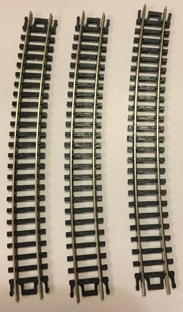
Sectional track
When it’s time to assemble the track sections, take care with the joints: Make sure that both rails slide into, not on top of, each rail joiner. Also, the rail should fit snugly into its rail joiner. A loose connection may let the rails work their way out of alignment, possibly leading to derailments. It can also prevent electricity from flowing reliably from one track section to the next, leading to locomotives stalling from lack of power. If in doubt, throw out the old joiners and use new rail joiners. (Hint: They’re cheap!) Finally, make sure that the flow of the track is smooth, without kinks at the rail joints that can derail trains later on.
Over the last twenty years, sectional track with the ties implanted in molded plastic roadbed has replaced “conventional” sectional track in most train sets.
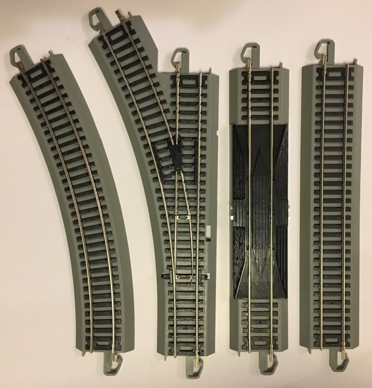
Sectional track with integrated roadbed. Notice that the diverging route keeps curving beyond the frog (the black plastic casting where the opposite-side rails cross); this is typical of sectional track with or without integrated roadbed.
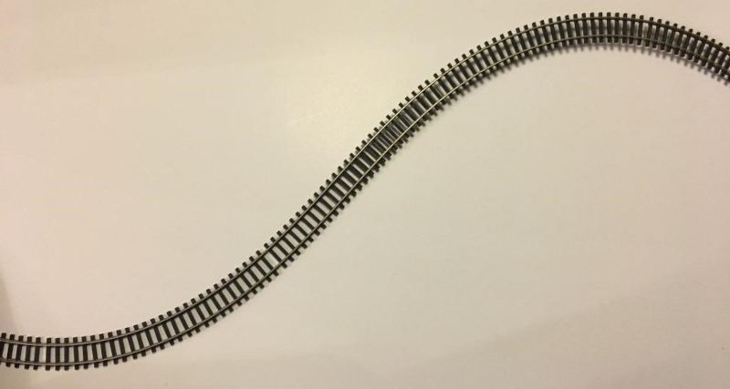
Flex track, as its name implies, is track that is flexible.
Flex track typically comes in lengths of about two to four feet, depending on scale, with three-foot (or 1 meter) sections being common in HO. There are two main types: Track with gaps between the ties only under one rail (with that rail held loosely so it can slide back and forth), and track with gaps alternating under one rail, then the other, and so on.
Flex track
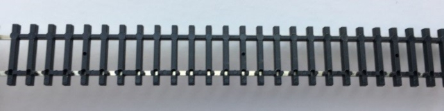
All gaps under one rail
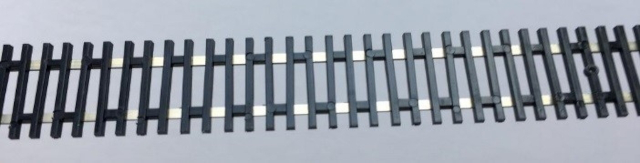
Alternating gaps
-
You can create almost any radius you want, and start and stop curves anywhere. Avoid the temptation, though, to twist flex track into curves that are sharper than the minimum radius you chose when you planned your layout.
-
You can use “easements” into and out of curves, just like the prototype railroads do. Instead of changing immediately from straight track to the curve’s radius, the curve starts almost imperceptibly, and gradually tightens to the final radius. Think of it like gradually turning your steering wheel when the highway curves, rather than keeping the steering wheel straight then suddenly snapping it to the curve. On a model railroad, easements don’t just look more realistic: They help reduce the misalignment between body-mounted couplers on longer cars. And, with flex track, easements are easy! Search the web for “model railroad track easement” for good explanations of how to lay out an easement.
-
Longer sections of track lead to fewer rail joints, with fewer chances for mechanical or electrical problems.
-
You will have to cut rail. Get a good pair of flush-cutters (e.g. Xuron “Track Cutter”), and NEVER use them to cut anything harder than nickel silver rail.

-
Flush-cutters will make a clean cut across the rail while mangling the excess part you’re cutting off. But you don’t care about that excess part anyway! If the excess part is long enough to use elsewhere, turn the cutters around and make a new cut leaving a clean end on the rail you had just cut off, with just a short section of rail (with both ends mangled) to throw out.
-
At each rail joint, trim one or two ties from the ends of the rails. This will leave room for the rail joiners.
-
Use the points of the flush-cutters to cut the plastic; with practice, you’ll be able to avoid nicking the base of the rail. After the track is installed, slide those ties (with the spike detail removed, and maybe sanded down a bit on the underside so they’ll fit) back under the rail joiners to look like a continuous strip of ties.
-
After making a cut, even with flush cutters, use a jeweler’s file to file the end of the rail smooth: The file should be almost parallel to the rail to file off any burrs and add a small, slight taper. This allows the rail joiners to slide on much more easily.
-
On curves, put the “sliding” rail on the inside of the curve.
-
If a curve will be longer than a full length of flex track, you can solder two lengths of flex track together while they’re straight. Then, bend them to the desired curve and install them (trimming rails and ties at the ends as necessary).
-
#4 turnouts are good for tight industrial districts with lots of track in a small area. Use them if your largest locomotive is a 4-6-0 or 2-8-0 or a four-axle diesel, and your cars are no more than 50 scale feet long.
-
#6 turnouts work in yards and on branch lines, with steam locomotives with a two-wheel trailing truck (4-6-2 or 2-8-2) and car lengths of up to 70 scale feet. Smaller, older six-axle diesels can also be used here.
-
For mainline trains with 2-8-4, 4-6-4, or larger steam locomotives, or the latest mammoth diesels, and full-length passenger cars or 89-foot automobile rack cars, you’ll want #8 turnouts.
-
Shinohara turnouts are no longer manufactured but can still be found at some hobby shops and on the Internet in in codes 70 and 100. While perhaps more challenging to wire reliably than Walthers turnouts, they are well-made and reliable.
-
The “Building A Turnout” video series on Fast Tracks Tools’ YouTube channel is informative and inspiring!
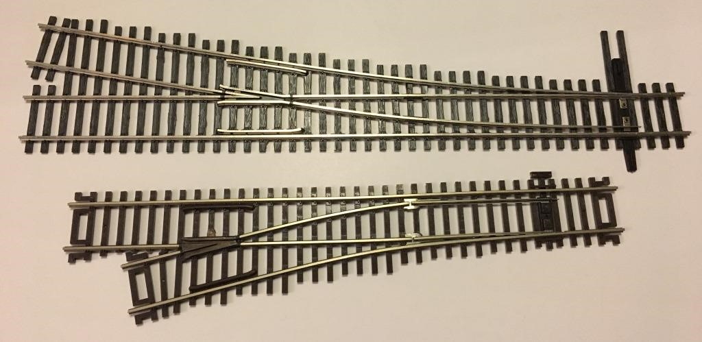
Walthers #6 (top) and Atlas Custom Line #4 (bottom) turnouts

Close-up of Atlas Custom Line #4 turnout, showing how the diverging route is straight except between the frog and the points (image coming soon!)
S-curves, where a curve in one direction leads directly into a curve in the other direction, don’t just look unrealistic. With body-mounted couplers, they can also derail your cars. A car on a curve to the left has its coupler hanging out to the right of the track. If it’s coupled to a car that’s already on an adjacent curve to the right, i.e., an s-curve, that car’s coupler is offset to the left. In many cases, the couplers can’t reach that far, so the lighter car gets pulled off the track.
Tips to avoid s-curves:
-
Have a length of straight track between opposing curves. This straight track should be at least 1.5 times (1 1/2) the length of your longest car. A straight length twice as long as your longest car is preferable.
-
Use easements (see “Flex Track” above).
-
Use turnouts with numbered frogs, where the diverging route is straight through and beyond the frog.
-
Be vigilant around “hidden” s-curves:
-
Crossovers between multiple tracks.
-
The beginning of a siding parallel to the mainline.
-
If you’ve heard a few model railroaders in conversation, you may think that we have a secret code for talking about track.
Yes, we have a code, but it’s no secret: “Code” refers to the height of the rail in thousandths of an inch. I.e., code 100 is 100 thousandths of an inch high, or one-tenth of an inch: 0.100”. Code 55 is 0.055” high, code 148 is 0.148” high, etc. Note that this refers only to the height of the metal rail, not the total height of the ties and rail.
Metal rail joiners, for mechanical and electrical connection between sections of track, are available where you buy the track itself. Be sure to choose a rail joiner compatible with the code of rail you’re using.
-
To avoid a short-circuit when using turnouts with all-metal frogs that aren’t internally insulated from the rest of the turnout. E.g., Peco and older Shinohara turnouts.
-
To avoid a short-circuit at a wye or reversing loop.
-
To divide a layout with DC (Direct Current) control into multiple blocks, for independent control of two or more trains.
-
To divide a large layout with DCC (Digital Command Control) into “power districts”, so that a short circuit in one area won’t shut down operation in other areas of the layout.
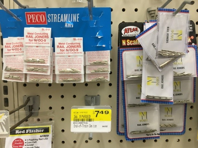
Rail joiners: metal
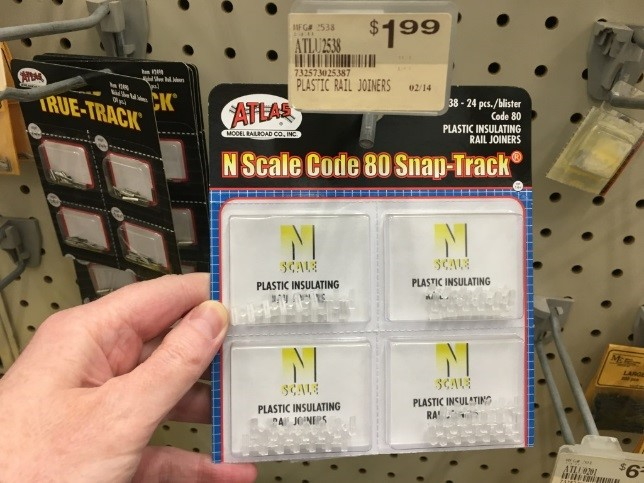
Rail joiners: plastic
Roadbed
-
Trains become very noisy when the track is laid directly on plywood.
-
Roadbed, especially types with beveled edges, elevates track around the surrounding countryside to look just like a well-built mainline on a prototype railroad.
Cork roadbed comes in strips just a bit wider than the track. These strips have a rectangular cross-section but are cut almost all the way through at a 45° angle, down the center of the strip. Peel the two halves of the strip apart, and fasten one half down with its back against the track centerline that you’ve marked on the plywood sub-roadbed. Then, lay the other half back-to-back with the first half. Be sure to stagger the joints in the two halves.
After the cork is secured in place, lightly sand it to provide a smooth, flat surface on which to lay your track. Sand the top edge of the beveled edge of the roadbed, too, to eliminate the “flash” where the two strips were pulled apart: This will make it easier to apply ballast later (after you’ve wired and painted your track). After sanding, if your model railroad is located in a humid environment, it is wise to give it two coats of latex paint before laying the track down. Pick a color paint similar to the ballast you will use. Cork is porous and will absorb moisture. This causes expansion that can distort the trackwork attached to the roadbed.
Foam is a recent addition to the model railroader’s repertoire of roadbed materials. Some modelers use products aimed at the home improvement market, such as garage door weather stripping. Other products, such as the Woodland Scenics roadbed pictured below, are specifically aimed at us model railroaders.
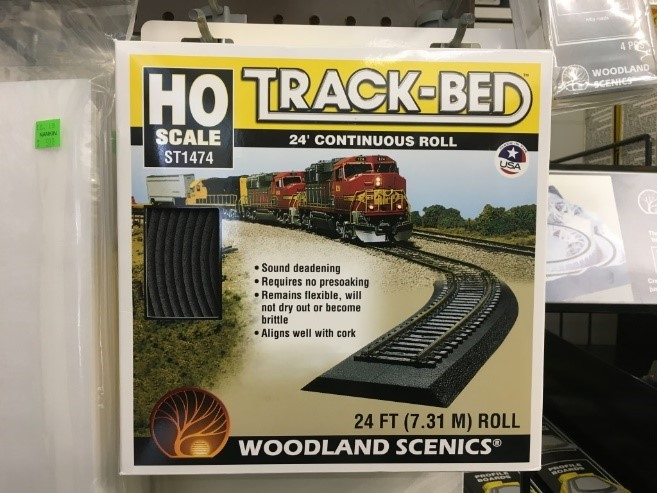
Woodland Scenics’ “Track-Bed” foam roadbed
Homasote is a pressed-paper board, available in 4’ x 8’ or 2’ x 4’ sheets, ½” thick, at home improvement stores. It has excellent sound deadening properties, and holds track spikes and track nails very well. (See “Fastening Track Down”, below.)
Fastening Track Down
Many brands of commercial track include holes in the ties for track nails (spikes), i.e. small thin nails available at hobby stores among the track components. In some cases, the holes are partial (to avoid visible holes on the top of the ties) and need to be drilled out from below. In most cases the hole is in the center of the tie; in Walthers and Shinohara turnouts they are right beside the base of the rail. For the latter, an option is miniature track spikes, which are also used for hand-laid track.
To avoid the unsightliness of nail heads at regular intervals in the middle of the track, you can glue the track down. This can give a much better appearance but can be much harder to change at a later date.
Controlling Turnout (Switch) Points
-
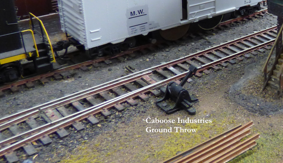
Ground throws, e.g., from Caboose Industries. These plastic mechanisms mount with nails or adhesive to a roadbed “pad” beside the turnout’s throwbar, similar to where a switchstand would be located on a prototype turnout. The ground throw’s actuating arm includes pins to engage a hole in the turnout’s throwbar. You may have to trim the ground throw’s actuating arm and/or the end of the turnout’s throwbar.
-
Mount an electric slide-switch to the roadbed next to the throwbar, with a steel wire to link the switch to the throwbar. Choose a switch whose motion is just slightly more than the motion of the points. When you slide the switch, the points move.
-
Mount a cable linkage from a control knob on the fascia at the front edge of the layout to a device under the layout such as a “Blue Point” switch machine, or a “BullFrog” from Fast Tracks.
-
Use a slow-motion “stall-motor” electric switch machine under the layout. A widely available brand is the “Tortoise” by Circuitron.
-
In the past, twin-coil solenoid switch machines were popular. These days, they have largely been replaced by the above methods, with good reason: Twin coils were noisy, could over-stress some turnouts, and either placed a large load on the layout power supply (trains would slow down when you activated one) or needed complex capacitor-discharge circuits.
Conclusion
-
This video by Bruce DeYoung, MMR® shows an easy way to weather track with washes of water-based rust-colored paint. https://www.youtube.com/watch?v=t4aicgy0aJQ
-
In this video, Bruce DeYoung, MMR® shows how to install cork roadbed. https://www.youtube.com/watch?v=QCJW6jgGOQI&feature=youtu.be
-
This video by Bruce DeYoung, MMR® focuses on installing cork roadbed under turnouts. https://www.youtube.com/watch?v=zctfWRcMNu0&feature=youtu.be
Many thanks to the members (particularly Bruce Wolf) of Division 6 of the North Central Region, NMRA for permission to use their content in this part of the Guide.